- Calculate the Laplace Transform $X(s)$ of the signal $x(t)$:
- Calculate the Inverse Laplace Transform $g(t)$ of the transfer function $G(s)$:
- Write the transfer function to a step input of a second order system characterised by:
- Static gain $G(0)=5$
- Damping ratio $\xi=0.5$
- Settling time $t_s=3 s$
- No zeros
- Plot the qualitative behaviour of the step response of the system:
- For the system $G(s)$ defined above, calculate:
- Its steady state value $y_\infty$ to a step input (when $t \rightarrow \infty$)
- Its settling time $t_s$
- If the system oscillates, calculate the period $T_\omega$ of the oscillation
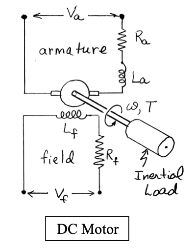
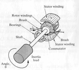
DC Motor Transfer Functions
The figures below represents a DC motor attached to an inertial load.
 |
 |
 |
The input voltage can be applied to either the field or the armature terminals. The voltages applied to the field and armature sides of the motor are represented by $V_f$ and $V_a$.
The resistances and inductances of the field and armature sides of the motor are represented by $R_f$ , $L_f$, $R_a$, and $L_a$. The torque generated by the motor can be assumed to be related linarly to $i_f$ and $i_a$, the currents in the field and armature sides of the motor, as follows:
$$ T_m = K i_f i_a \;\;\;\;(1) $$From the equation above, clearly to retain the linearity, one current must be kept constant, while the other becomes the input current.
This makes it possible to have field-current or armature-current controlled motors. We will focus on the field-current motor for our analysis.
This means that in a field-current controlled motor, the armature current is kept constant, while the field current $i_a$ is controlled through the field voltage $V_f$.
$$ T_m = K i_f i_a = K_m i_f \;\;\;\;(2) $$where $K_m$ is defined as the motor constant. The motor torque increases linearly with the field current.
1. Write the Transfer Function from the input current to the resulting torque of the previous equation
For the field side of the motor the voltage/current relationship is $$ V_f =V_R +V_L = R_f i_f +L_f (di_f dt) \;\;\;\;(3) $$
2. Write the Transfer Function from the input voltage to the resulting current
$$ \frac{I_f(s)}{V_f(s)} = \text{_____} \;\;\;\;(4) $$3. Write the Transfer Function from the input voltage to the resulting motor torque
$$ \frac{T_m(s)}{V_f(s)} = \text{_____} \;\;\;\;(5) $$4. Discuss how the motor torque behaves with respect to different input signals. For example, one could analyse the system order and type and verify its response to a step input in field voltage, or anything else that you thing is relevant to understand how the motor behaves.
We can now add load to the motor and verify how its behaviour changes.
The motor torque $T_m(s)$ is equal to the torque delivered to the load, and this relation can be expressed as:
$$ T_m(s) = T_L(s) + T_d(s) \;\;\;\;(6) $$where $T_L(s)$, and $T_d(s)$ is the disturbance torque (e.g., external forces acting on the load).
We can calculate the rotational motion of the inertial load summing moments (see Figures above):
$$ \sum{M} = T_L - f\omega = J \dot{\omega} \;\;\;\;(7) $$where $f$ is due to friction, and $J$ is the load inertia. $\omega$ is the rotation speed of the motor.
5. Write the Laplace transform of the load torque $T_L(s)$ using equation (7) above
where $\Omega(s) = \mathcal{L}(\omega(t))$
6. Given that the relationship between position and angular velocity $\omega$, refine the equation you have just calculated to explicit the rotor position $\theta$ (hint: $\dot\theta = \omega$)
7. Put together equations (2,4,6) and calculate the transfer function of the motor-load combination
$$ \frac{\theta(s)}{V_f(s)} = \text{_____} \;\;\;\;(9) $$8. Discuss the resuting system (order, dominant pole approximations, what happens when parameters change, select specific values for the parameters and draw its step response)
9. Draw a block diagram of the field controlled DC motor from the field voltage to the position output using all the relevant equations calculated so far. Make sure you include the disturbance $T_d(s)$ as per equation (6).